
High Accessibility Cabinet Insert


Motivation
Watching grandparents and parents get older, the struggle of day-to-day activities generally increases. One of the most recurring issues the older generation go through at least once a day is their inability to reach dishes, glassware, and other things on the topmost shelves of a kitchen. Not only is it difficult for them to use things such as stepstools, it also becomes increasingly dangerous, as with age, a fall from any height could be catastrophic.
With this scenario in mind, a user-friendly cabinet insert would be a very effective way to combat this issue. However, many existing models of cabinet designed to fit these requirements operate using two linkage arms, and thus, have a higher material and manufacturing cost. One of the goals of this project is to reduce the overall cost and time to manufacture for a device that would be as effective as other benchmarked devices.
This called for a design with only a single linkage arm. The device must also reduce the amount of force required to lift the nominal load by 50%. The insert, consisting of gas spring-assisted lowering shelf, will allow the user to “pull” items at a significant height down to a more reasonable level. The completed shelf does function as designed, however, the challenge of maintaining structural integrity with only one link arm was a large roadblock throughout this project.
Analysis
A large portion of the analysis for this project came in specifying the necessary cross-sectional size and type of material used for the linkage arm. After basic statics and strengths analysis with the forces involved in loading this device, a cross-sectional area of 1.5"x 1/4" of 1018 was seen to be adequate for this device. Combined stresses for this cross-sectional area of 1018 showed the max stress to be around 19.5ksi, giving this link arm a safety factor of around 2.7 when fully loaded at 60lbs.
Link Arm
Gas Spring
Gas traction springs have a "pull-in" force, as seen in figure 1, which have a constant force acting inwards towards the center of the device. This was implemented in the device in order to dampen the descent speed of the shelf, as well as help the user return the shelf to its up position. Upon summating forces with the max load, it was determined that the spring force must always be less than 226lbs to allow for rotation. The next step to specifying a spring was inputting the various forces of each model, and choosing the one that was high enough to help dampen the descent/raise the shelf, but also not low enough to barely make a dent on the systems descent speed. A rough estimate of the users force of 5lbs was chosen as a target force for the user to have to generate to pull the device down. In order to achieve that, a spring force of 43 lbs was needed. However, upon searching for traction gas springs, the only available model was a 30lbf gas spring. A second analysis, using the 30lbf gas spring was completed to find the new user forces that would be necessary to pull down and push up a shelf at full load. Using the newly specified 30lbf spring, the user will only have to generate 3.48lbf to initiate the descent of the shelf, and will require around a 20lbf push to initiate the gas spring at full load. However, due to the angle at which the gas spring acts on the link arm, this user force quickly decreases as the load moves up, to a low of 2.85lbf, well below the 50% threshold.

Figure 1.
Slide and Fasteners
Forces on fasteners were taken into consideration whilst choosing fasteners for this project. The "stop bolt", which acts as a stop for the link arm in its horizontal state, was originally specified to be a 5/8" bolt. However, upon consulting with a fastener professional, a new form of analysis was done on the bolt, as the only forces acting on it would be direct shear, which changed the necessary cross sectional area of the grade 8 bolt to be a 1/2" diameter bolt.
The slide prevents the ascent of an empty shelf during loading and unloading of the device. The optimal cross-sectional area was decided on after finding a max bending stress that was well under a material’s yield. Originally, a turned down piece of aluminum was going to be used for this slide. However, a much easier solution would be to use a 1/2" clevis pin. A zinc plated low carbon steel clevis pin was chosen for ease of purchase and its material properties. The analysis shows that the stresses acting on this pin will create a stress that is less than half the yield for the material. This is more than acceptable for this application.
Testing & Results
Test 1: User Force Analysis
The first round of testing took place before the installation of the second arm. This test involved loading the shelf up to various weights in different configurations on the shelf, and measuring the amount of user force necessary to initiate shelf movement. These values were then compared to values estimated previously. Figure 4 shows tabulated results for the first test can be seen.
Test 1: Results
Figure 4
The user forces to push the shelf up were of critical importance, and emphasized in the requirements for this project. Figures 5 and 6 show the results of test one in regards to these upward user forces.
Figure 5.
Figure 6.
Test 2: Link Arm Deflection
The second round of testing was a simple deflection test. This test was meant to understand two aspects of the analysis of the link arm. One being, at maximum load, the link arm must not yield at all. For safety reasons, the safety factor on the shelf is 3, and the max load is intended to be 20lb. 20lb x 3 = 60lb, which dictated the test weight for this test. There were many issues that came along with this testing. While the link arm was designed to hold 60lb, it was clear the connection between the shelf and the arm was not, as the whole thing "sagged" while applying weight. This made it impossible to get a good deflection reading. So, as seen in figure 7, the mount block / link arm assembly was removed from the housing. The 60lb weight was hung on the tip of the arm, and a dial indicating mic was placed underneath the tip to measure deflection to the nearest .001"
Test 2: Results

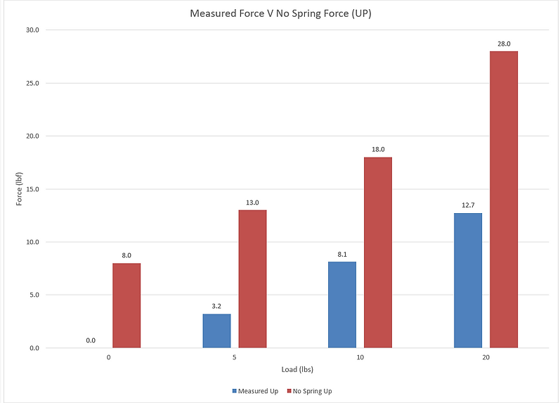

Figure 7.

Upon measuring the deflection of the tip of the link arm, a very large discrepancy between the predicted deflection and the actual deflection is seen. This is due to a lot of unforeseen error in the original testing technique. As can be seen in figure 1, the surface which the block is mounted to “hangs off” the base of the table. This probably accounts for some of the deflection seen. Also, the back pin on which the arm swivels is smaller than the hole in which it rests i.e. there is a lot of clearance. Due to this, there is a lot of play involved, so when the weight is applied, some of the “deflection” is not necessarily material deflection, but just movement of the entire arm in general. For better results, this test will be recreated once the second link arm is installed.
Table 1

The predicted "up" forces were much higher than the actual forces. This may be due to the angle of the force the user applies to the device when in use, compared to the predicted angle. The "predicted angle" was done in a conservative manner, i.e., predicted if the user applied a force mostly in a way parallel to the link arm. The measured up forces were much lower than the forces the user would have needed to apply without the spring, showing the success of the gas spring.
Matthew Leal
Mechanical Engineering Technology Student
Central Washington University

Construction
Overall, the manufacturing for this project was estimated to be around 23 hours, and ended up being around 38 hours, nearly double the original estimate. This was due to the excessively long amount of time dedicated to machining the mount block correctly.
Mount Block:
During the machining operations seen on the mount block, the threaded hole was threaded in the wrong direction through the mount block, after all four holes had already been machined. Below, the hole layout for the mount block can be seen in Figure 2.
Figure 2: Mount Block hole layout
To machine the stock for the mount block down to the correct thickness, a lot of material had to be taken off. By hand, this would have taken many hours of painstaking precision and effort. Instead, a CNC Mill program was written to perform the necessary face milling. A copy of the written program can be seen in Appendix X of the written report. This program was run many times, each time with the Z height offset changed to cut to the correct depth. By running this program 10 times, it took the correct amount of material off the part. Figure 3 shows the mount block during the CNC milling operation.
Figure 3: CNC Mill Op
Shelves and Housing:
The manufacturing of the shelves was quick and painless, using wood glue and a nail gun to fasten the wood together. This was much cheaper and faster than the original plan to manufacture the shelves from aluminum. Figure 4 shows the stock wood used to create both the shelves and the housing.
Future Improvements:
There are many improvements that can be made to the manufacturing process to improve efficiency and make the entire process more lean. For example, a CNC program could be written to face mill the stock down to size for the mount block, and then drill the holes. This would not be a time-consuming program to write, and would save hours on the manual drill press.
Purchasing the correct stock would also save an immense amount of manufacturing time, as if the correct stock with the correct thickness were to be purchased, an entire manufacturing step could be skipped.


Contact
Project Proposal
Below, a complete project proposal for this project can be found in PDF form.This document contains the full design, analysis, construction, testing, budget, and scheduling data over the duration of the projects timeline.


Budget and Schedule
Time management was very crucial in order to complete this project on schedule. Below, the Gantt charts for both winter and spring show the actual charted construction time compared to a schedule estimated before construction began. Generally, the project was ahead of schedule the entire year. However, as soon as rework began, the project lost steam as there were many unforeseen issues implementing the rework changes.
The project was completed on time, however.
WINTER 2016

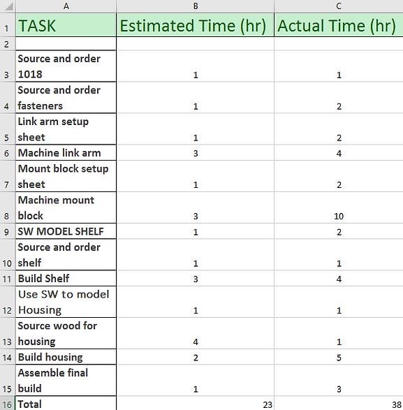
Above, an hour by hour breakdown for each task within the Gannt chart above can be seen.
SPRING 2017
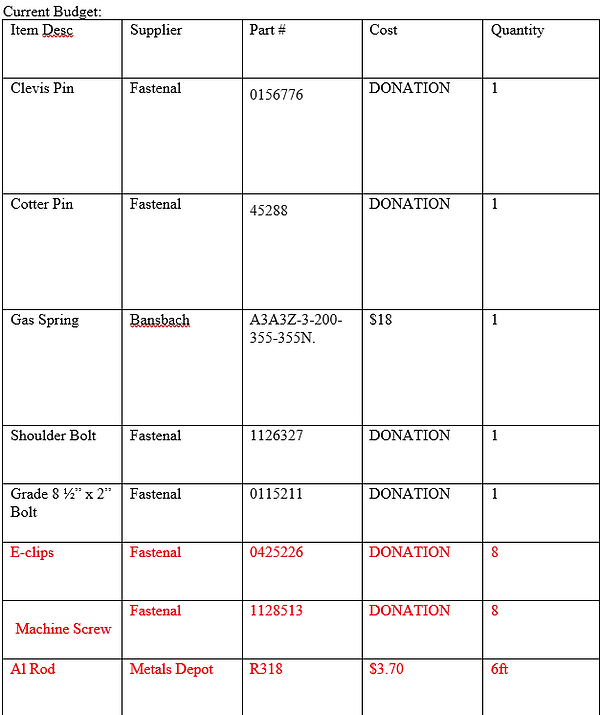
Budget


Single Arm Actuation
The arm actuated as planned, and brought the shelf down to a very acceptable height. The locking mechanism, shown in the video above, was also very effective at keeping the shelf locked in place in its "down" position.
Immediate Issues
-
Unforeseen fitment issues (Solidworks and personal machining skills are not perfect)
-
Different loadings on the shelf had large effect on gas spring effectiveness
-
"Stronger" gas spring proved to be more effective. However, it led to safety issues.
-
40lb gas spring caused an unloaded shelf to violently "snap" back into upright position
-
Take an efficiency hit in order to keep device safe
-
-
-
Extreme deflection of link arm in upright position (figure 6)
-
Incorrect design and analysis
-

Figure 6: Link arm deflection
Figure 4: Housing and Shelf stock
Figure 5: Link Arm Machining
In order to address the issues that were prevalent after the initial build during the winter, a rework period was implemented throughout spring. Figure 8 details the planning and design phase for a second linkage arm to be added to this design. Although it did contradict the original design goal of only a single arm, it was decided to be absolutely necessary for the success and safety of the device.

Figure 8 shows preliminary planning and design for the second link arm
The second link arm, made from 3/4" square steel tubing, attached to the shelf and housing at different locations than the original link arm. By having the second link arms rotational axis in a different position than the first arms axis, it helps prevent the entire shelf from rotating during descent, and helps it remain parallel to the ground.
GOALS
Eliminate deflection when upright
Eliminate torsional deflection when extended
Keep shelf parallel to ground during actuation
Optimize all part connections for rigidity
Rework
Figure 9 : Dual arm actuation axis of rotation demo
Second arm implementation


Figure 10: Before and after second arm implementation
After the implementation of the second link arm, the change was drastic. The deflection seen in the original design was almost null. Even with weight loaded, as can be seen in figure 10, the shelf walls remain essentially parallel to the housing walls. This was a tremendous success. Figure 11 shows the actually implemented dual link arm and its effectiveness in keeping the shelf parallel. While it did help, the loose connections between part connections still allowed for some play between the shelf and the arms.
Figure 11: Actual two arm actuation
Connection Rigidity
In order to improve the overall rigidity of the system, brackets were machined and implemented to this device. These connections, now strengthened by the steel brackets, performed much better than before (Figure 12).


Figure 12: Two examples of rigid connections on the second link arm


